
Problem statement: why thermal failure is the immediate threat
High‑density electrosurgical generator boards concentrate significant power into small PCBs and that concentration turns thermal management from an engineering detail into a safety imperative. Reports from device design reviews at exhibitions such as the international medical expo show engineers increasingly confronting component overheating, premature MOSFET degradation and localised delamination—failures that translate directly into clinical risk and field recalls. The problem is architectural as much as it is material: without a coherent dissipation strategy, power density overwhelms conventional board techniques.
Root causes in board architecture
Failures typically trace to a few recurrent architectural choices. Tight component placement increases thermal coupling; insufficient copper planes limit conductive spread; and absent or improperly dimensioned thermal vias prevent heat flow to heat sinks. Added to that, poor selection of thermal interface material (TIM) and overreliance on single‑device cooling create hotspots. These are not abstract faults: they manifest as raised junction temperatures, altered switching characteristics in power stages and accelerated electromigration on critical traces.
Practical design measures to restore thermal balance
Effective mitigation demands changes at multiple levels. First, adopt distributed power staging: split load across parallel MOSFETs to lower per‑device dissipation. Second, specify internal copper pour and arrays of thermal vias beneath high‑loss components to channel heat toward a dedicated heat sink. Third, choose TIMs with known thermal resistance values and test them under expected compression levels. Finally, consider mechanical integration—chassis conduction paths and forced convection channels often outperform exotic PCB laminates at reasonable cost. Each tactic reduces junction temperature and lengthens mean time between failures.
Testing and regulatory checkpoints
Thermal validation cannot be an afterthought. Alongside thermal cycling and thermal imaging, compliance with IEC requirements and EMC robustness is essential. When referring to EMC under IEC 60601‑1‑2, ensure your test plan explicitly covers these sub‑chapters:
– Electrostatic discharge (ESD) immunity
– Radiated RF immunity
– Conducted RF immunity
– Surge immunity
– Magnetic field immunity
– Voltage dips and interruptions
– Radiated emissions
– Conducted emissions
Run board‑level thermal soak tests that replicate duty cycles observed in clinical use and retain samples for the recommended lifecycle interval; commonly accepted retention for accelerated ageing is 14 days for bioburden incubation when applicable.
Common mistakes and how to avoid them
Design teams often prioritise signal integrity over heat paths, misjudge ambient conditions or under‑specify component derating. Avoid these pitfalls by using cross‑discipline reviews: have PCB, thermal and firmware engineers sign off on power profiles. Ensure simulation results map to bench measurements—CFD models predict trends but must be validated with thermal cameras and thermocouples. And do not treat EMC shielding as separate from thermal design; added metal boxes change conduction and convection markedly—so iterate.
Anchor: field evidence and industry context
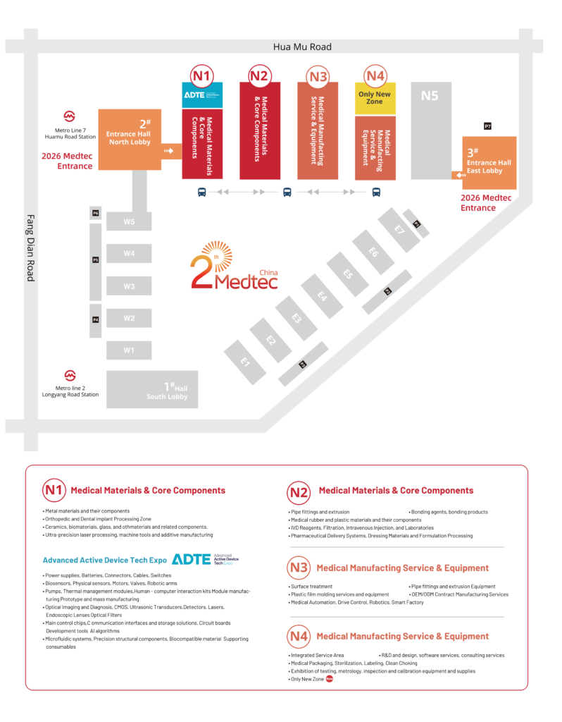
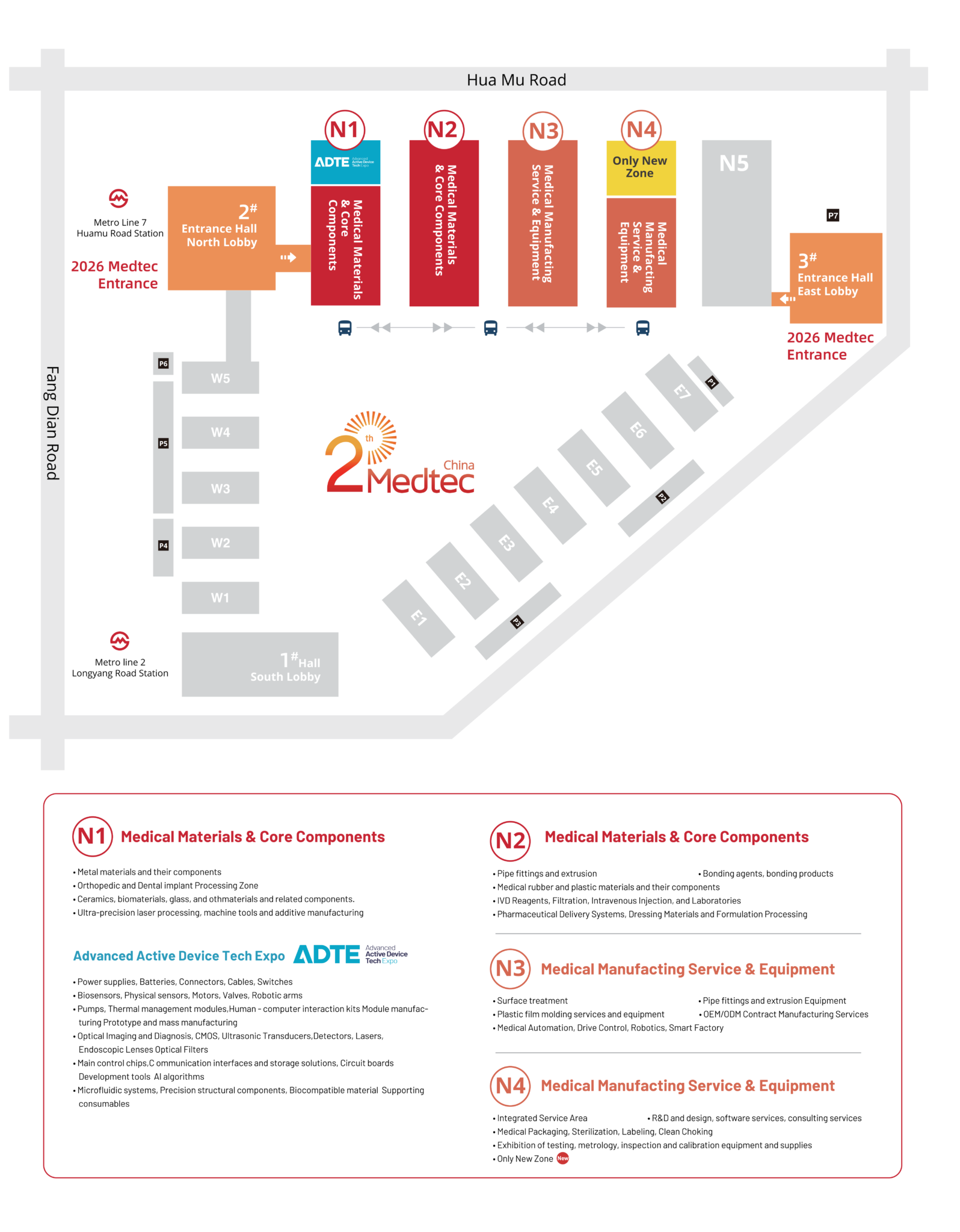
Observations from product demos and workshops at Medtec China in Shanghai underscore that practical fixes—better copper distribution, modest increases in board area and improved TIM choice—yield measurable reductions in junction temperatures. Regulators and purchasers increasingly ask for documented thermal budgets and failure‑mode analyses; IEC 60601‑1 remains the go‑to reference for safety architecture. This is practitioner EEAT: guidance grounded in standards and in on‑site lessons from trade exhibitions and clinical engineers.
Advisory: three golden rules for selection and verification
First, set a clear thermal budget expressed as maximum junction temperature plus a safety margin and verify it under full clinical duty cycle. Second, demand both simulation and empirical proof: thermal simulations must be corroborated by chamber and in‑situ measurements. Third, require modular redundancy—design so that no single component exceeds the board’s allocated thermal budget. These metrics give procurement teams concrete pass/fail criteria and reduce field surprises.
Final thought: rigorous thermal architecture protects patients and product reputations—Medtec. –